June 2006
APPLICATION NOTE NO. 66
Routine Maintenance for the SBE 32 Carousel Water
Sampler
June 2006
![]()
Application note in pdf format
This Application Note reviews corrosion precautions and routine maintenance for the SBE 32 Carousel Water Sampler. The reliability of the Carousel is sustained by establishing proper handling practices.
Rinse the entire Carousel with fresh water after each cast.
The Carousel’s trigger mechanism is made of titanium. The titanium is coated with Tiodizing; this product is similar to anodizing aluminum. The Tiodized surface is water lubricating and should never be oiled with petroleum or silicon-based products. Rinse the trigger mechanism with fresh water after each cast and clean it periodically with warm, soapy water. If the trigger mechanism sticks after this cleaning, remove the latch assembly and immerse the whole assembly in warm, soapy water. See Removing / Replacing Latch Assembly below.
Large zinc anodes provide corrosion protection:
Check the anodes occasionally to verify that they are securely fastened and have not eroded.
All screws that are exposed to seawater have been generously lubricated with an anti-seize compound, Never-Seez Blue Moly, manufactured by Bostik (available through marine hardware stores). When disassembling/reassembling the Carousel, re-lubricate these screws with Blue Moly or equivalent. This compound is electrically conductive, so be careful not to get it on circuit boards.
Note: Blue Moly is molybdenum disulfide and pure nickel flake in
pressure-resistant premium
grade grease, formulated without graphite, lead, or copper. See Bostik’s
website (http://www.bostik-us.com/TDS/TDSFiles/NSBlueMoly.pdf)
for the specifications.
Removing Latch Assembly
 |
 |
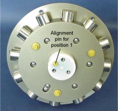
- Mark the location of trigger 1 (from the retainer disk) on the trigger mount disk to aid in reassembly.
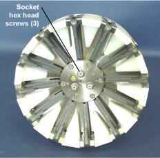
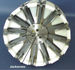
- Remove the Phillips-head screws (eight for 32C and 32SC, six for full-size 32). Lift the retainer disk from the top of the latch assembly.
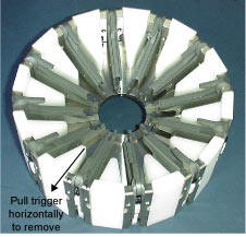
- Pull the desired trigger(s) horizontally from the trigger mount disk. Mark the trigger(s) to aid in reassembly.
 |
 |
 Replacing Latch Assembly
- Remove the hardware from underneath the lower guard ring.
- Begin to pull the lifting bail up, until it is above the lower guard ring/adapter plate/hub assembly connection.
- Remove the hardware from the legs of the lifting bail.
- Pull the lifting bail out of the upper guard ring.
NOTE:
There are plastic insulators on the underside of the following connections:
- Lower guard ring/adapter plate/hub assembly - for lifting bail
- Upper adapter plate - for pylon
Verify that the insulators have not fallen out before reinstalling the pylon and lifting bail.
![]()
Last modified: 06 Apr 2007
Sea-Bird Home Phone: 425-643-9866 Fax: 425-643-9954 E-mail: seabird@seabird.com